Sistema de Lubricacion Motor
3508B Engine - RENR1330
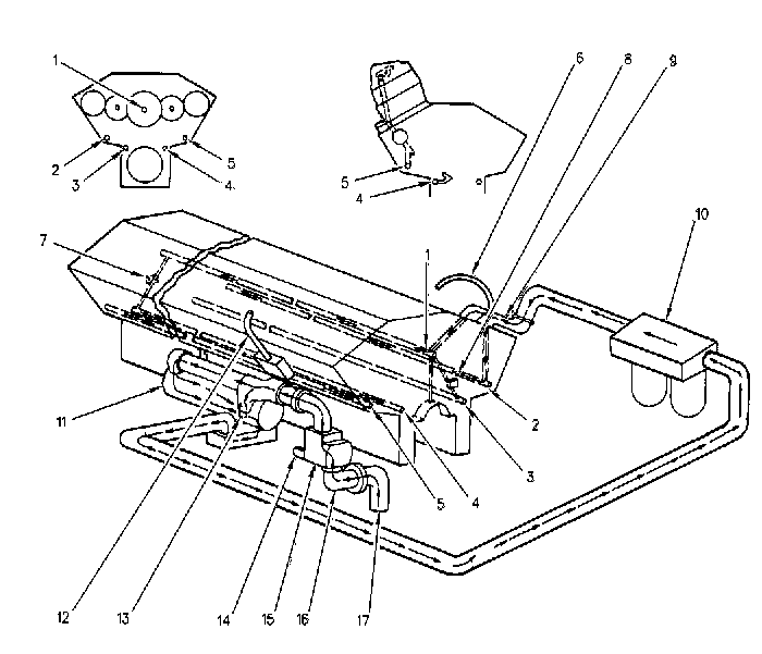
Ilustración 1 Este sistema utiliza una bomba de aceite (15) con tres engranajes.
Los engranajes de la bomba son impulsados por el tren de engranajes
delantero. La bomba de aceite del motor extrae el aceite del colector de
aceite del motor a través de la campana de succión (17) y el codo (16).
La campana de succión tiene una rejilla para poder limpiar el aceite.
lustración 2 g00281793
Ilustración 3
Ilustración 4
Ilustración 5
|
C27 and C32 Engines for Caterpillar Built Machines - SENR9937
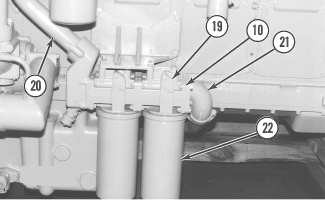
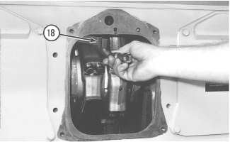
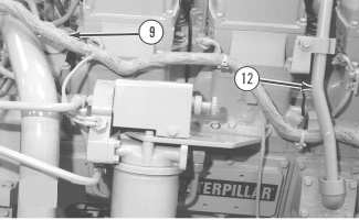
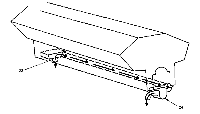
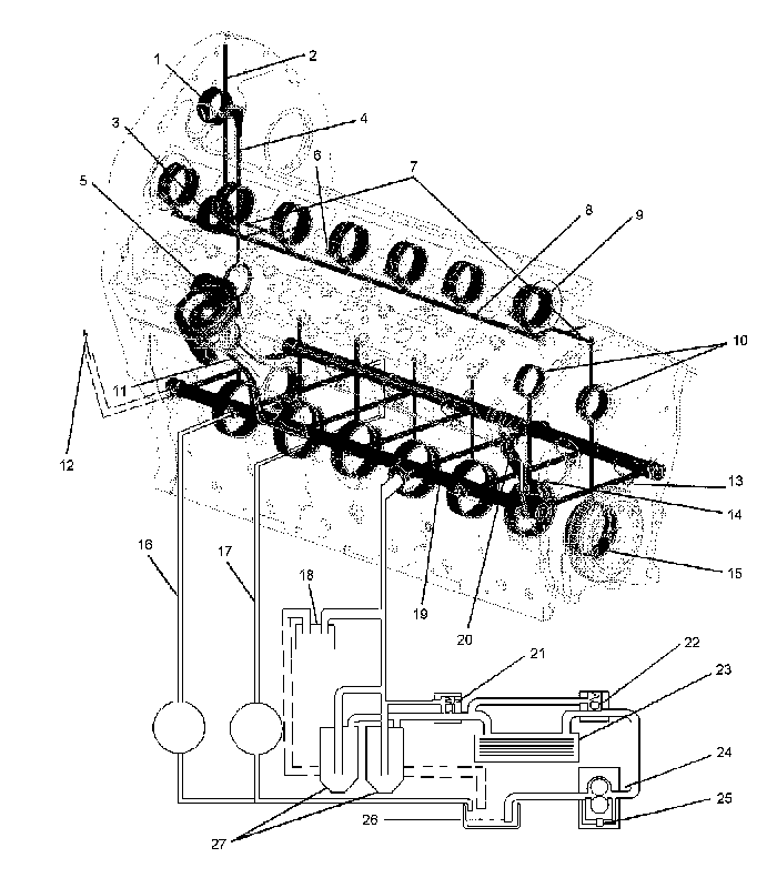 Ilustración 1 Diagrama del sistema de lubricación La bomba de aceite (24) está montada en la parte inferior del bloque de motor, dentro del colector de aceite (26). La bomba de aceite (24) extrae el aceite del colector de aceite (26). A continuación, el aceite fluye a través de un conducto hasta el enfriador de aceite (23). El aceite fluye entonces a través de los filtros de aceite (27). El aceite puede fluir hacia dentro del conducto de aceite principal (19) desde el lado derecho o izquierdo del bloque. La ubicación del suministro de aceite que ingresa depende de la ubicación de los filtros de aceite que pueden estar ubicados en cualquier lado del bloque. El aceite fluye entonces a través de un conjunto de orificios transversales hacia el lado opuesto del conducto de aceite. El conducto de aceite principal (19) distribuye el aceite a los siguientes componentes: cojinetes de bancada del cigüeñal (15), boquillas de enfriamiento del pistón (13), extensión del conducto de aceite (20), tubería de suministro de aceite del turbocompresor (16), tubería de suministro de aceite del turbocompresor (17) y cojinetes de engranajes locos delanteros activos (10). El conducto de aceite principal (19) distribuye también el aceite a los mandos accesorios traseros a través de una tubería de aceite externa (12) . El aceite ingresa al cigüeñal a través de los orificios de la superficie de apoyo (muñones) del cojinete de bancada (15). Los conductos conectan la superficie de apoyo (muñón) del cojinete de bancada (15) con la superficie de apoyo (muñón) de la biela (11). El aceite fluye hacia arriba a través de un conducto perforado en la biela al cojinete de pasador del pistón. La extensión para el conducto de aceite (20) está ubicada en la esquina delantera derecha del bloque de motor. La extensión del conducto de aceite (20) suministra aceite al cojinete del engranaje loco delantero inferior (14) . El aceite fluye al cojinete de engranaje loco delantero activo (10) y alrededor del cojinete (10) al conducto de aceite de la culata de cilindro (7). El aceite fluye entonces al conducto de aceite de la culata de cilindro (8) y al conducto de aceite (6) de los cojinetes de árbol de levas (9) y los balancines. El aceite del cojinete de la rueda loca trasera inferior (5) se suministra desde un conducto conectado al último cojinete de bancada trasero del cigüeñal (15). El aceite también se suministra desde el cojinete de bancada trasero hacia la tubería de aceite trasera (4) y hacia el conducto de aceite de la caja trasera (2) para el cojinete del engranaje loco trasero intermedio (3) y el cojinete del engranaje loco trasero superior (1) . Este circuito de aceite funciona normalmente a una presión de 214 kPa (31 lb/pulg2) a velocidad baja en vacío y de 400 kPa (58 lb/pulg2) a velocidad nominal. La válvula de derivación de la bomba de aceite (25) limita la presión del aceite que viene de la bomba de aceite (24). La bomba de aceite (24) puede poner más aceite en el sistema del necesario. La válvula de derivación de la bomba de aceite (25) se abre a medida que la presión del aceite aumenta. Esto permite que el aceite que no sea necesario regrese al lado de succión de la bomba de aceite (24) . El aceite frío con alta viscosidad causa una restricción al flujo de aceite a través del enfriador de aceite (23) y el filtro de aceite (27). La válvula de derivación del enfriador de aceite (22) y la válvula de derivación del filtro del aceite (21) se abrirán si el motor está frío. Esto proporcionará lubricación inmediata a todos los componentes. La bomba de aceite (24) envía el aceite frío a través de las válvulas de derivación, alrededor del enfriador de aceite (23) y el filtro de aceite (27) y hacia el conducto de aceite principal (19) en el bloque de motor. Cuando el aceite se calienta, la diferencia de presión en las válvulas de derivación disminuye. Esto cierra las válvulas de derivación. Esto produce un flujo normal de aceite a través del enfriador de aceite y a través del filtro del aceite. Las válvulas de derivación también se abren cuando hay una restricción en el enfriador de aceite (23) o en el filtro de aceite (27). Mediante esta acción, se lubrica el motor si se restringen el enfriador de aceite (23) o el filtro de aceite (27). Las presiones de apertura de las válvulas de derivación varían con las aplicaciones. Existe una cámara de enfriamiento del aceite formada por el labio forjado en la parte superior de la camisa del pistón y la cavidad que está detrás de las ranuras del anillo en la corona del pistón. El flujo de aceite de la boquilla de enfriamiento del pistón (13) ingresa a la cámara de enfriamiento a través de un conducto perforado en la falda y retorna al colector de aceite (26) a través del espacio libre entre la corona y la falda. Los cuatro agujeros taladrados desde la ranura del anillo de aceite del pistón al interior del pistón drenan el exceso de aceite del anillo. El respiradero de aceite permite que los gases de escape de los cilindros escapen del cárter durante la operación del motor. La derivación de gases de escape se descarga a través de la caja del volante hacia un tubo preformado tendido hacia la atmósfera. Esto evita que se acumule presión y se puedan producir fugas en los sellos o en las empaquetaduras. Nota: Los motores equipados con un filtro de aceite auxiliar (18) recogerán aceite en un orificio. El aceite filtrado retornará al colector de aceite (26) . Sistema de renovación de aceite (si tiene) El propósito del sistema de renovación de aceite (ORS) es aumentar la frecuencia del intervalo de cambios de aceite. El objetivo del ORS también es disminuir la cantidad de aceite usado que se debe eliminar. No se acorta la vida útil del motor cuando se realiza esto. El ORS dosifica el aceite del motor que se introduce en el suministro de combustible de la máquina. Este aceite se consumirá en el motor durante el proceso normal de combustión. El Módulo de Control Electrónico (ECM) del motor calcula la cantidad de aceite que se dosifica. Esta cantidad está basada en el factor real de carga o en el combustible que consume el motor. El ORS tiene un tanque de aceite de compensación. El tanque de aceite de compensación es un depósito de aceite que reabastece el aceite que la válvula de renovación del aceite saca del cárter del motor. El consumo normal de aceite continuará bajando el nivel del aceite en el cárter. La adición continua de aceite nuevo permitirá prolongar la duración del aceite. La revisión de los informes del análisis S·O·S del aceite permitirá determinar si ha ocurrido un problema y si es necesario cambiar el aceite. El ORS está integrado con el motor y con el sistema electrónico de la máquina. El sistema electrónico consta de sensores, interruptores, el ECM y el Sistema Monitor. El sistema electrónico informará al operador de un desperfecto del sistema o de una advertencia. Se pueden detectar las siguientes advertencias:
Nota: La electrónica del motor desactivará automáticamente el sistema para evitar los posibles daños al motor. El sistema se puede volver a arrancar mediante la corrección del problema y al restaurar el suministro eléctrico.
|
Oil Renewal System - RENR8160
| NOTICE |
|---|
| Read and understand this publication before using the Oil Renewal System (ORS). Otherwise, reduced engine life will result. |
The purpose of the ORS is intended to increase the oil change interval. The purpose of the ORS is also intended to decrease the amount of used oil in need of disposal. The life of the engine is not shortened when this is accomplished.
General Description
The ORS meters engine oil that is introduced into the fuel supply of the machine. This oil will be consumed in the engine during the normal process of combustion. The amount of oil that is metered is calculated by the engine's Electronic Control Module (ECM). This amount is based on the actual load factor or on the fuel that is consumed by the engine.
The ORS is equipped with a makeup oil tank. The makeup oil tank is an oil reservoir that will replenish the oil that is removed from the engine crankcase by the oil renewal valve. Normal oil consumption will continue to lower the oil in the crankcase. Continually adding new oil will allow the life of the oil to be extended. Reviewing the reports of the S·O·S Oil Analysis will determine if a problem has occurred and if the oil needs to be changed.
The ORS is integrated with the engine and with the electronic system of the machine. The electronic system consists of sensors, switches, the ECM, and the monitoring system. The electronic system will notify the operator of a system malfunction or of warning. The following warnings can be detected:
- Problem with the metering valve
- Low fuel level
- Plugging of the secondary fuel filter
- Low makeup tank oil level
- Low engine oil pressure
The electronics of the engine will automatically turn off the system in order to avoid possible damage to the engine. The system can be restarted by correcting the problem and cycling the power.
Benefits
The benefits of the ORS include the following items:
- A reduction or elimination in the number of oil changes
- A reduction or elimination of the disposal of used engine oil
- An increase in the availability of the machine
- An overall improvement in the quality of the oil over the service life of the engine
Reference
Refer to Engine Data Sheet, LEKQ6070, "Blending Used Crankcase Oil With Diesel Fuel" and Engine Data Sheet, LEKQ6071, "Blending Used Crankcase Oil With Diesel Fuel For Use in Caterpillar Heavy Duty Diesel Engines" for additional information.
The following recommendations must be followed for engines during operation with the Oil Renewal System (ORS):
- Caterpillar Multigrade Diesel Engine Oil (DEO) is recommended. Refer to Operation and Maintenance Manual, SEBU6250, "Caterpillar Machine Fluids Recommendations".
- Check the crankcase oil level daily and keep a log of all the additions of engine oil.
- Check the oil level of the makeup oil tank daily and keep a log of all the additions of engine oil.
- Every 250 hours obtain an S·O·S Oil Analysis.
- Every 500 hours change the engine oil filters and the secondary fuel filters. Change the filters sooner if the monitoring system indicates that the filters need to be changed.
- Change the engine oil if the results of the S·O·S Oil Analysis indicates that the engine oil needs to be changed.
| NOTICE |
|---|
| It is the user's responsibility to make sure the above items are managed during the life of the engine with the ORS turned on. Failure to do so may result in shortened engine life or a catastrophic engine failure. |
Engine Oil
For recommended engine oil to use, refer to Operation and Maintenance Manual, SEBU6250, "Caterpillar Machine Fluids Recommendations".
Record Oil Additions (Daily)
Keeping a daily maintenance log of all of the additions of oil is necessary for determining whether the ORS is working properly. The daily maintenance log is also necessary for establishing the correct rate for adjusting the oil metering. Illustration 1 shows an example of the additions of oil during a 500 hour period. The daily maintenance log will also be the source of the total amount of oil that has been added since the last oil change. This information is needed at the time of each oil analysis.
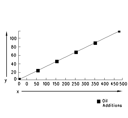
| Illustration 1 | |
| (y) The amount of oil that
is added is shown in gallons. (x) Service hours |
|
Caterpillar S·O·S Analysis (Every 250 Hours)
Be certain that the following tests are performed on every sample of engine oil:
- Wear metals
- Infrared analysis
- Total Base Number (TBN)
- Chemical and physical properties
When an oil sample is submitted for analysis, the following information must accompany the sample:
- The number of hours on the oil since the last S·O·S Oil Analysis
- The quantity of new oil that has been added to the engine since the last S·O·S Oil Analysis
The Caterpillar S·O·S Oil Analysis will help establish a baseline for wear metal and infrared limits throughout the life of the engine. The S·O·S Oil Analysis will also indicate if the ORS is working properly or if an abnormality is occurring in the engine such as water leaks in the oil, bearing wear, etc. The following graph shows the amount that the metal will wear as the hours on the engine increase with use of the ORS
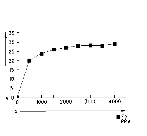 .
| Illustration 2 | |
| (y) PPM Fe (x) Service hours |
|
Note: If this type of trend is not occurring the following items may not be correct: the operation of the system, the rate for metering and the operation of the engine. Refer to Systems Operation, "Troubleshooting".
Change Engine Oil Filters (Every 500 Hours)
Only use Caterpillar engine oil filters. Every 500 service hours change the engine oil filters.
Change Engine's Secondary Fuel Filters (Every 500 Hours)
Only use Caterpillar high efficiency fuel filters. The use of fuel filter that has a rating of 2 microns is required with use of the ORS. Blending used engine oil with diesel fuel will increase the particle count in the fuel that is delivered to the engine. The 2 micron fuel filter will remove smaller particles from the filtered fuel supply to the engine which will provide greater protection to the electronic fuel injectors.
The indicator for the fuel filter differential pressure will be activated if the filters become plugged. A Level 1 monitoring system warning will be displayed to the operator. If this problem occurs, the plugged fuel filters will not turn off the ORS. Change the fuel filters in order to correct the problem.
3500B Engines
Ver imagen
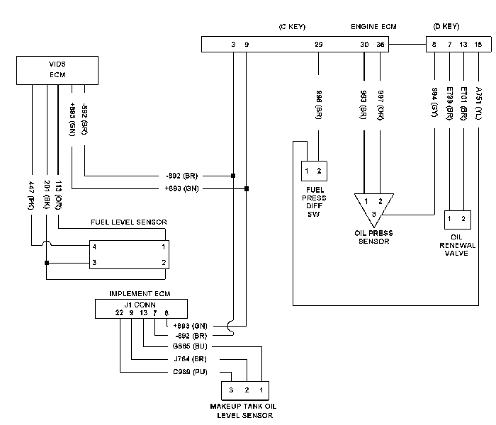
Illustration 1
Electrical schematic for the oil renewal system
Ver imagen
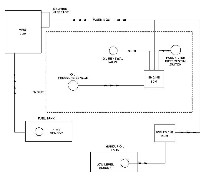
Illustration 2
System schematic for the oil renewal system
Ver imagen
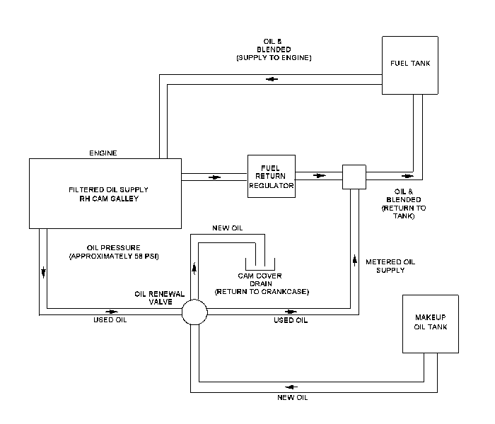
Illustration 3
Oil and fuel flow schematic for the oil renewal system
Ver imagen
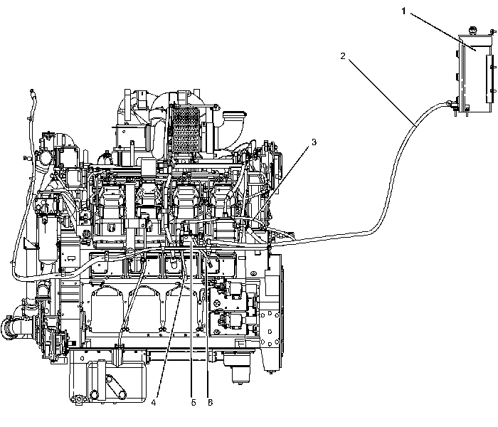
Illustration 4
Oil renewal system
(1) Makeup oil tank
(2) Makeup oil line
(3) Metered oil line
(4) Oil supply line
(5) ORS valve
(6) Oil drain line
Ver imagen

Illustration 5
Oil metering group
(3) Metered oil line
(4) Oil supply line
(5) ORS valve
(6) Oil drain line
(7) Fuel return line
(8) Oil and fuel blend return to tank line
C32 Engines
Ver imagen

Illustration 6
Electrical schematic for the C32 Engines
Ver imagen

Illustration 7
System schematic for the C32 Engines
Ver imagen
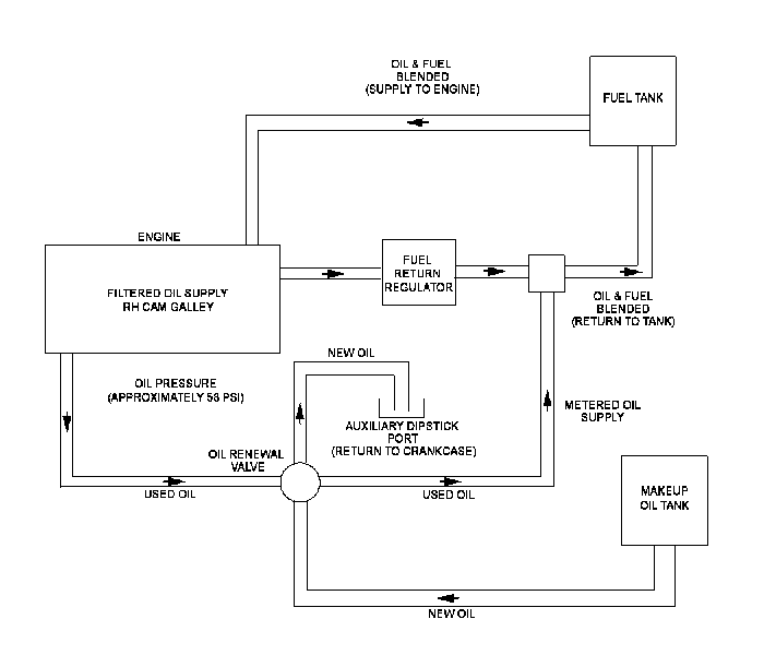
Illustration 8
Oil and fuel flow schematic for the oil renewal system
Ver imagen

Illustration 9
Oil renewal system
(1) Makeup oil tank
(2) Makeup oil line
(3) Oil supply line
(4) Metered oil line
(5) Oil drain line
(6) ORS valve
Ver imagen

Illustration 10
Oil metering group
(3) Oil supply line
(4) Metered oil line
(5) Oil drain line
(6) ORS valve
Ver imagen
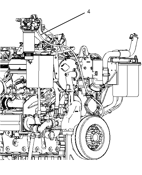
Illustration 11
Oil metering group
(4) Metered oil line
Normal Operating Parameters (3500B Engines)
In order to activate the Oil Renewal System (ORS), the following conditions must be met:
- The engine speed is between 1100 and 1850 rpm.
- The jacket water coolant temperature is
between
63 to 107 °C (145 to 225 °F) . - The engine has been running for five minutes.
- The engine oil is above the makeup tank's oil level sensor.
- The machine's fuel tank level is above ten percent capacity.
When the ORS is activated, the time for activation of the oil metering valve is determined by the ECM. The time of the activation is based on the actual load factor or on the fuel that is consumed by the engine.
Normal Operating Parameters (C32 Engines)
In order to activate the Oil Renewal System (ORS), the following parameters must be met:
- The engine speed is above 1100 rpm.
- The jacket water coolant temperature is
between
63 °C (145 °F) and107 °C (225 °F) . - The engine has been running for five minutes.
- The engine oil is above the low level switch.
- The level of the makeup tank is above low.
- The machine's fuel tank level is above ten percent capacity.
When the ORS is activated, the time for activation of the oil metering valve is determined by the ECM. The time of the activation is based on the actual load factor or the fuel that is consumed by the engine.
Checking the flow from the Oil Metering Valve
Use the following procedure in order to determine if a problem has occurred with either the oil metering valve or with the lines that lead to the valve and the lines that lead from the valve.
- Disconnect the rubber hose from the tee in
the fuel return line and connect that end to a small container. Cap the tee
before you start the engine.
- Start the engine and then use the override
on Caterpillar Electronic Technician (Cat ET) to start the actuation of the
oil metering valve.
The valve will be on for ten seconds and off for ten seconds. This will repeat until the override is turned off.
For proper operation , each cycle delivers
17 cc (0.57 fl oz) of oil to the container that is attached to the hose.If the oil is not delivered, the system could be turned off or the system could be disabled. If no oil flows and the oil does not fill the container, check the following items:
- Makeup tank oil level
- Fuel level of machine
- Plugged lines
- Electronic faults
Electrical Troubleshooting
Refer to the engine's Troubleshooting Manual or the machine's Troubleshooting Manual for information on troubleshooting diagnostic codes and event codes.